
1. Introduction
Modern satellite communication payloads require high directivity and multiple beams with large signal bandwidth to satisfy broad-band applications, such as multimedia and voice conferences. Therefore, an active phased array is ideal for such applications, since they can be configured in orbit to provide the bandwidth in demand and increase overall system utilization [5,7,8].
The total transmission quality of a communication satellite using a multibeam phased-array antenna system is most dependent upon the nonlinear distortion of the solid state power amplifier (SSPA) modules [7].
This distortion brings about intermodulation (IM) interferences. The closer to the compression point due to the most power efficiency means more IM product levels that degrade carrier-to-interference ratio (C/I) associated with beam steering direction. So,accurate modeling of these IM beams helps control the IM interference, thus allowing the SSPAs to be operated with minimum back-off since fewer margins are needed. This results in a more efficient array that requires a lower system DC power with reduced mass and cost of the satellite [8]. Intermodulation products (IMPs) in an active-array antenna have characteristics that are different from those in lumped active circuits and systems. For multiple-beam satellite digital communication systems, signal suppression and IMP interference in amplifiers may degrade the bit-error rate 1 to 5 dB in comparison to passive antennas. The presence of interfering signals may result in an increase of the array beam-width, side-lobe level, null depth degradation, as well as changing the null positions [7]. Sandrin [9] previously analyzed the radiating patterns of third- and fifth-order IM products of active arrays. In his analysis, he derived the phase gradient for the mth-order intermodes and used generic transfer functions for a nonlinear amplifier. His analysis incorporates approximations appropriate for limited field of view arrays (as in the case of an earth-looking antenna on a geosynchronous satellite) and for small percentage bandwidth. Kohls et al. [7] presented simulation and experimental results for KU band arrays. They used a Bessel series to fit the above-mentioned model of a KU-band array for predicting third-order IM product beam patterns. Meanwhile, Maalouf and Lier [8] studied IM estimation in an active phased-array theoretically and experimentally.
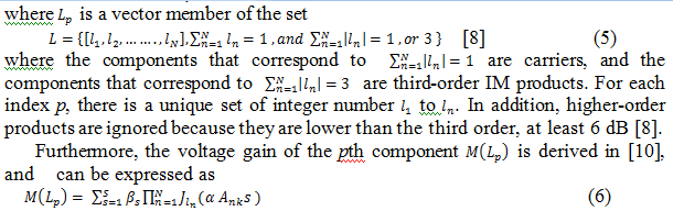
All of these studies involved narrow band signals. This implies that the amplifier characteristics are frequency independent over the frequency band of interest. However, while having broadband input signals, or systems including wide-band amplifiers and relatively narrow-band components, a frequency-dependent quadrature model is required [1]. Ehsan Johari and Haleh Karkhaneh [3] introduced An amplifier model with frequency-dependent parameters is considered. To investigate nonlinearity effects in a phased-array antenna and validated by experimental data.
For base stations, the major issue is linearity, as the down-link signal must be highly-linear in order to achieve a small error rate and a good quality of reception in mobile terminals. Power amplification of RF signals faces a problem of achieving high linearity and efficiency at the same time. Efficiency is maximized when a PA operates with a small back-off, i.e. close to the saturation region. However, in this mode of operation, nonlinear distortions are produced, which degrade the system linearity. It means that efficiency and linearity are mutually exclusive requirements. A trade-off between them is usually sought for each particular application [10,6]. Linearization techniques for nonlinear microwave power amplifiers have been around for decades, ranging from analog techniques such as feedforward linearization [6,2] and Cartesian loop feedback correction [6], to digital techniques such as digital predistortion linearization [6,4].
This paper consists of six sections. In Section 2, power amplifiers (PAs) are modeled. Then, the mathematical modeling of IM products is calculated in Section 3. Next, the radiation farfield pattern is considered in Section 4, a digital predistortion linearizer is explained in Section 5, and finally the functionality of the proposed integrated system is introduced in section 6.The simulated results are presented in Section 7, and conclusions are given in Section 8.
2. Nonlinear SSPA model
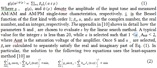
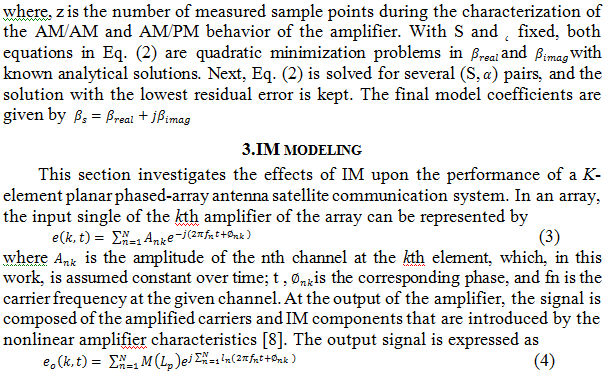
The main idea of quadrature modeling technique is using a complex envelope instead of real narrow band signals; thus, there is no carrier information in the complex envelope except the modulation information. This point is important from the viewpoint of computational efficiency. The SSPA characteristics are modeled with series of Bessel function coefficients because of their ability to quickly converge to the nonlinear characteristics of the amplifier and model the IM products at the output of the amplifier. The mathematical model provides the gain and phase insertion of each carrier and IM component at the output of the SSPA; therefore, it is suitable to incorporate into the antenna phased-array model. Therefore this method can achieve the necessary accuracy for active phased array systems [ 9,10 ].
The nonlinear behavior of the amplifier can be expressed by the following Bessel function series:
- Radiating array model
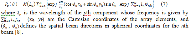
The radiation pattern of the array is modeled analytically as the product of the element pattern and the array factor, assuming identical element patterns over the array and no mutual coupling. These assumptions are relatively accurate for patch elements with distances of 1.5 times greater than lambda, which are considered in the modeling. Furthermore, it is assumed that the fundamental TM10 mode is propagating in the microstrip patch antenna. Here, the radiating elements are modeled in an array environment, and the array factor’s far-field array factor radiation patterns are calculated for both the carriers and IM products based on excitation coefficients generated by the IM algorithm. The far-field array factor radiation pattern for each component in any spatial direction is given by the coherent sum of the corresponding SSPA output component given in Eq. (7), expressed as
- Linearizer model
As processing power has become cheaper and more powerful over the last two decades, mainly due to the great advances in digital signal processing (DSP), digital predistortion linearization has become one of, if not the most cost efficient linearization technique available for microwave power amplifiers. The overall goal is to design a block which compensates for nonlinear effects present in the power amplifier in digital baseband, allowing us to utilize digital signal processing techniques to achieve great precision [2]. Prior to designing a digital predistorter, a model of the nonlinear microwave power amplifier is often required in order to estimate its inverse. the next step is to estimate the model parameters, either by an direct approach with least squares methods, or by an daptive/iterative approach using i.e. an adaptive filter such as the least mean square (LMS) filter [10], or the recursive least square (RLS) filter [4]. The pre-distortion technique (DPD) has high efficiency, adaptive ability and good Inter Modulation suppression. As it is operated before the power amplifier, which means the signal processing does not consume large power.
The best way to solve this problem is suitable Horison system with discrete time (i.e. digital signals) takes the following mathematical model:
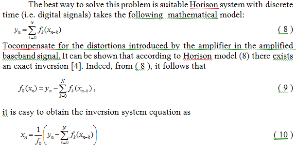
Thus, if there is a reversible function f0 , the analytical model of the form (8) implies its precise handling (9). These functions can be used to implement the nonlinear characteristics of the microwave PA linearizer.
In the proposed model the basic functions f0, f1, f2, have been chosen to be spline functions, in particular, piecewise linear splines and the cubic parabola (third-degree polynomial).
6. Integrated system model
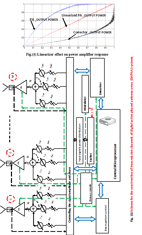
A functional block diagram of the proposed integrated active phased antenna array transmission system is shown in fig.( 1 ). It consists of M radiating elements, M solid statepower amplifiers (SSPAs), and N independent beamformerchannels and M attenuators and phase shifters for each beamformer. The proposed integrated model functionality can be described briefly as following :
- Antenna array radiating elements: form the antenna aperture and consist of a set of identical near-omnidirectional radiators (dipole, slot, horn, waveguide), usually located in the form of right-angled or skew-angled nodes ,
- Power amplifier modules: are usually implemented in the form of electric vacuum or solid-state devices, which are connected directly to the antenna elements in order to eliminate the need for RF feeder line at a high power level, and thereby significantly reduce the high-frequency loss ,
- Linearizer module : is responsible for the transmission factor adjustment (the gain and the electrical length) of each power amplifier module via linearization of PA characteristics,
- which in turns achieves a higher efficiency performance due to the enhancement of power losses, which are generated by IMD signals ,
- The central microprocessor : determines the complex coefficients of transmission channels in accordance with a predetermined shape and position of the antenna array pattern in the space ,which are determined by beam pattern control unit and simultaneously an adaptive monitoring of PAs outputs is achieved via a command control program with linearizer The output signals are multiplied with the vector of coefficients that take into account the internal state of the system (failures, amplitude and phase calibration) for correction of antenna array pattern.
- Modulator: adaptive phased antenna array emitted signals can be modulated in the excitation stage or at PA elements,
- Beam pattern control unit: generates the necessary distribution of amplitudes and phases of the input signals to the array radiation elements. This system comprises a set of power amplifiers, a set of phase shifters and a set of matching circuits. Each radiator element is connected in series with the matching circuit, power amplifier and phase shifter to form a single adaptive phased array channel. Usually, all channel elements are combined into a unitary structure which is called a module,
- Amplitude and phase control unit : generates the required phase and amplitude distribution of excitation signals. Usually it consists of a set of controlled delay lines or phase shifters, and attenuators,
- Input power distribution unit: can be implemented in a passive or active forms. Passive type is based on the parallel, serial, or other multilevel scheme by using different types of power dividers (feeder excitation ) or by the optical system (spatial excitation). Active type is intended to be included at different levels (stages) of cascaded amplifiers. Active types are used in cases when the exciter power is not sufficient to excite all PAs of adaptive phased array system, or when it is required to build an array by using the same active devices, i.e unifying or standardizing them,
- Matching devices, which can serve as impedance transformers and non-dissipative stubs have been installed to reduce the reflection losses from the antenna array radiators in the scan mode (or changing the array radiation pattern) and providing stable operating conditions at PAs outputs,
- Non-reciprocal devices — valves or circulators can be installed for isolation PA and radiators, and
- In addition, the construction of any adaptive phased array systems may include some other units such as ; power supply , functional check control and cooling units, where there are three factors , which are based on the construction of adaptive phased antenna array system : the location of the phase shifters in each transmitter sub-channel, the number of distribution systems, and the presence of cascaded PA conversion (frequency multiplication stages).
- Results
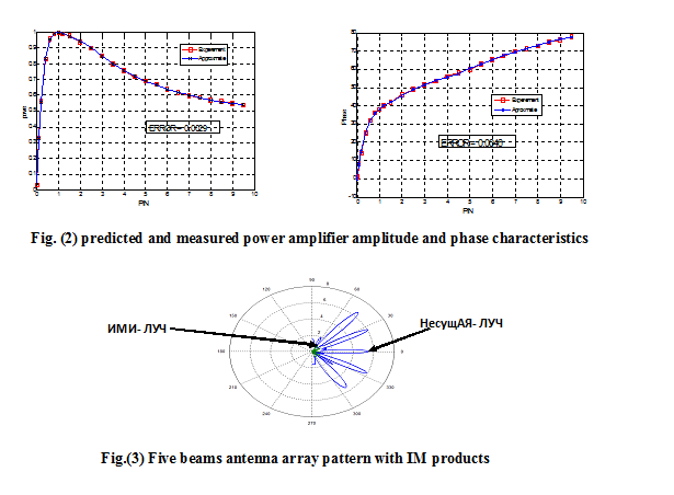
In this paper, a two-beam S-band array has been studied, which is comprised of sixteen patch antenna elements in a 1 _ 16 configuration. The amplifier characterization is described by measuring the single tone AM/AM and AM/PM of a subset of the SSPA with a frequency of 3.5 GHz to represent the nonlinear response of the element. Then, the amplifier is modeled as described in Section III with ten terms of Bessel functions. The agreement between the measured and predicted amplitude and phase characteristics is shown in Figure 2.
After PA modeling, the array is fed by five different tones 3500 MHz, 3450 MHz , 3475 MHz 3525 MHz , and 3550 MHz and five beams are steered in [-50o , -25o , 0o , 25o , 50o ], in which the power is set at 0 dB total power input back-off (IBO) to represent the nonlinear operation of predicted carrier components in the compressed region. Figure 3 shows the predicted two carriers on the same graph, as well as the third order IM component when the array is operated at 0 dB IBO., each consisting of the zero elevation pattern cuts. The linearizer characteristics based on having the inverse of the predicted PA model by using Horison model is shown in figure 4.
- Conclusions
A main goal in an active transmitter array is to drive the amplifiers to be as saturated as possible (for optimal efficiency). In this paper, an sixteen-element integrated S-band phase array system is simulated by the Shimbo nonlinear amplifier model and digital predistortion linearizer model based on getting PA inverse by using Horison model. Also, the array far-field parameters, side lobe, and IM patterns are calculated in this paper. This analysis presents that interference can be predicted accurately and theoretically controlled in multi-beam phased-array satellite system. Hence, it reduces the necessary excessive margin. Therefore, with this reduction, transmitter power consumption will be decreased, and consequently, satellite consumption and mass will be reduced.
References
[1] Abuelma’atti M. T. Frequency dependent nonlinear quadrature model for TWT amplifiers. IEEE Trans. Commun. COM-32:982–986, 1973 .
[2] Cheong M.Y., Brunmayr P., M., and Laakso T. I. Prototype Implementation of Two Efficient Low-Complexity Digital Predistortion Algorithms , EURASIP Journal on Advances in Signal Processing, 2008.
[3] Ehsan Johari, Haleh Karkhaneh ,and Ayaz Ghorbani. Theoretical Approach to Estimate Intermodulations in Wideband Active Transmit Phase-Array Antennas, Electromagnetics, 50-59, 2012 .
[4] Haykin S. Adaptive Filter Theory, 4th ed. Prentice Hall, 2002.
[5] Hemmi C. Pattern characteristics of harmonic and intermodulation products in broad-band active transmit arrays. IEEE Trans. Antennas Propagat. 50:858–865 , 2002 .
[6] Kenington P. B., High Linearity RF Amplifier Design, ser. Artech House MicrowaveLibrary. Artech House, 2000.
[7] Kohls, E. C., Ekelman E. P., and Zaghloul A. I. Intermodulation and bit-error ratio performance of KU-band multi-beam high-power phased array. Proc. Antennas Propagat. Soc.Int. Symp. Dig. 3:1404–1408. 1995 .
[8] Maalouf, K. J., & E. Lier. Theoretical and experimental study of interference in multi beam active phased array transmit antenna for satellite communications. IEEE Trans. Antennas Propagat. AP-52:587–592. 2004.
[9] Sandrin W. A. Spatial distribution of intermodulation products in active phased array antennas. IEEE Trans. Antennas Propagat. AP-21:864–868 ,1973.
[10] Vuong X. T., and Henchey V. On the accuracy of the Shimbo approach to intermodulation and crosstalk calculations. IEEE Trans. Commun. COM-29:1076–1082, 1981 .
 [schema type=»book» name=»A PROPOSED INTEGRATED MULTIBEAM ACTIVE PHASED ANTENNA ARRAY TRANSMISSION SYSTEM FOR INTERFERENCE CANCELLATION IN SATELLITE COMMUNICATIONS» author=»Viktor ivanovich nefedov, Mohamed Atta Aboelazm» publisher=»БАСАРАНОВИЧ ЕКАТЕРИНА» pubdate=»2017-05-25″ edition=»ЕВРАЗИЙСКИЙ СОЮЗ УЧЕНЫХ_ 30.01.2015_01(10)» ebook=»yes» ]