
- Introduction
Currently sharply increased interest in environmental issues, which is primarily due to the ever-increasing contamination of the environment.
According to the latest data on the study of atmospheric pollution in industrial developed countries [1-4], the main sources of pollution are industrial and energy facilities and transport, which accounted for over 80% of the total amount of pollution. The major components of air pollution are gaseous compounds of carbon, nitrogen and sulfur, as well as solid and liquid aerosol formation, which are of particular concern for the normal functioning of humans and other biological objects [5-6].
Significant contamination of air space and its devastating effects on human health, climate and vegetation is also due to macroscopic leaks (or sometimes emissions) of natural gas pipelines and extensive fires, particularly forest areas.
Therefore, the creation of optoelectronic devices and systems with the best metrological parameters that enable the operational analysis of basic physical and environmental parameters, and distant monitoring of the atmosphere and air infrared environmental control of vast forest spaces (for detection of fires in the early stages of their development) and pipelines of natural gas is a very important task.
The present work is devoted to presenting the results of research and development work on the development and manufacturing of optical-electronic instruments for environmental purposes to explore the basic physical and ecological parameters of the atmosphere, as well as monitoring forest spaces and main gas pipelines.
- Optical-Electronic Measuring System for Atmospheric Transparency
Measuring complex called “The Field Optical-meteorological post-Machine (FOMPA)” [7], designed for continuous measurement of meteorological optical range, or the extinction of the atmosphere in the wavelength range from 0.35 to 1.1 microns, and the automatic processing of the results of the spectral transparency of the atmosphere in the range of from 1 to 14 microns.
Complex “FOMPA” is composed of two units: Optical-mechanical (OMU) and electronic control unit (ECU).
Optical scheme OMU is shown in Figure 1.
Optoelectronic device path is formed of three channels, measuring, controlling and of the background. Unlike remote (OMU) unit, which operates directly in the atmosphere, ECU and recording of the complex may be in the room or in the back of the auto laboratory for the distance control the operation of the equipment.
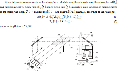
Figure 1. Optical Scheme of OMU Measurer of Spectral Transparency of the Atmosphere: 1-illuminating; 2-lamp ISSH-100-5; 3-parabolic mirror; 4,15-cellular hood; 5,11-screen; 6.23-protective glass; 7.13-iris aperture; 8-absorber of light; 9-mirror «Black»; 10-control lens; 12-photometer; 14-flat mirror; 16.17-mirror objectives; 18-round lens hood; 19-cylinder lens hood; 20-filter; 21-rotation axis; 22-aperture; 24-plane of FEU; 25-working volume of device.
A significant advantage of the above developed by us optical-electronic complex “FOMPA” compared to the currently operating (especially in the aviation services) similar devices [8] is the ability to provide for periodic monitoring sensitivity of apparatus in the time operating instructions manual and all measurements against the “black” mirrors which provides a high sensitivity reception system.
- The Metrological Characteristics of Equipment “FOMPA”
Metrological certification of equipment “FOMPA” conducted according to the specially developed program of metrological certification (AEL2.766.000PMA) [9]. When certification apparatus defined metrological characteristics indicated in Table 1.
Experimental studies of the metrological characteristics of the equipment “FOMPA” held in the chamber for an optical calibration, the description of which is presented in [10]. The list of all products used in the certification of the equipment, with its precision classes presented in [9].
Certification shall be subject to the sensitivity of the equipment, “FOMPA” to the value of the attenuation coefficient of the atmosphere. It is determined by recording the electrical signal output apparatus for measuring the attenuation in a clean atmosphere.
Table 1: Metrological Parameters of theEquipment “FOMPA”
|
The Name of the Metrological Characteristics and Units of Measuring |
Nom. Values |
Permissible Declinations |
| The sensitivity of instruments in the four wavelengths to the value of the attenuation coefficient of the atmosphere, [Km-1/mV] | A1 (0.35)
A2 (0.55) A3 (0.70) A4 (1.10) |
± 15%
± 15% ± 15% ± 15% |
| The ratio of the sensitivity of the equipment for measurements in clean air and carbon gas | 2.61 | ± 0.03 |
| The rms value of relative error in the measurement of the instrument attenuation coefficient of the atmosphere, no more than | ± 15% |
Electrical output devices “FOMPA” is linearly related to the attenuation coefficient of the atmosphere and the dependence of can be normalized as the main metrological characteristics of the equipment.
The main metrological parameters in equation (1) are the sensitivity of the equipment A (0.55).
The basic error of the measurement sensitivity of the outfit consists of errors of measuring circuits and errors in the determination of the coefficients. Additional hardware error associated with the impact of destabilizing factors such as changes in the ambient atmosphere, changing the supply voltage, vibration loads, etc.
Chimneys control exposed the threshold sensitivity of A (0.55) of the device, which is the measurement error of ± 15% (signal / noise ratio of 2.8).
When the ambient temperature changes from 273 to 313 K (00 to 400C) the additional error of the output signal does not exceed 20% of the basic error.
- Universal Infrared Spectral Radiometer “USR-A”
For the purpose of spectral and radiometric studies of atmospheric and thermal objects parameters in the wavelength range from 0.4 to 14 microns, we have developed and manufactured a universal spectral radiometer “USR-A”, a detailed description and principle of operation is presented in [11,12].
“USR-A” is designed to measure the spectral density of the brightness and radiation temperature (or drops) of point and extended sources of infrared radiation in the laboratory and field conditions, as well as for remote spectral analysis of hot gas facilities.
Structurally spectroradiometer made up of two parts: optical-mechanical (OMU) and the electronic control unit (ECU). The electrical connection between the units is by means of cables. Full spectral range of the instrument is covered by three sets of interchangeable filters and photo detectors sub bands: from 0.4 to 1.1 microns from 2.5 to 5.5 microns and from 8 to 14 microns. Optical scheme OMU is shown in Figure 2.
An Electronic Control Unit Constructively Desktop Performance: all organs and display controls are located on the front of the ECU. We note some of the benefits we developed IR spectroradiometer «USR-A» as compared to the existing close analogues (see for example [13]). To extend the functionality of spectral studies of thermal objects, except for the broadband interference filters for spectral regions from 0.4 to 1.1, from 2.5 to 5.5 and from 8 to 14 mm, the device is also provided with the ring tunable optical filters [14].
In order to eliminate chromatic aberrations in the optical system of the device includes two pairs (Fig. 2) Mirror projection lenses, in the focus of which are installed filters and photo detectors tipple.
At the end of this section, we note that after some design improvements in the optical system spectroradiometer «USR-A» (adding the input deflecting mirror) in [20] described in detail the method of air environmental control of forest spaces and gas main pipelines.
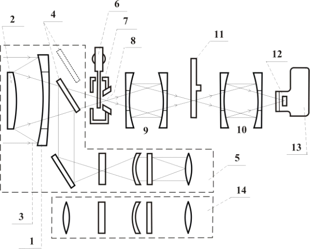 Figure 2. OMB Optical Scheme:1-Primary mirror lens; 2-secondary mirror lens; 3-radiation from the object; 4-retractable flat mirror; 5-sight; 6-modulator; 7-bearing cavity; 8-field stop; 9,10-projection lens; 11-disk interference filters; 12-sensitive area of the photo detector; 13-dewar of liquid nitrogen; 14-visual tube.
- The Metrological Characteristics of a Universal Spectroradiometer «USR-A”
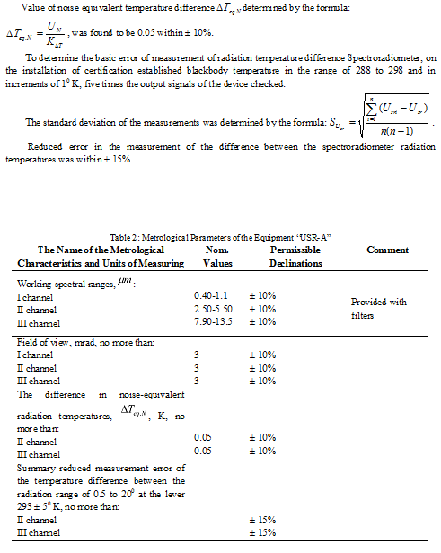
Metrological certification was conducted in accordance with the universal spectroradiometer specially designed program of metrological certification (AEL2.807.007PMA, [15]). In metrological evaluation determined device characteristics shown in Table 2. In carrying out metrological certification spectroradiometer “USR-A” to apply the necessary instrumentation and equipment referred to in [15]. In the same paper the conditions and procedure for certification are presented. Measurements to determine the difference between the radiation temperature equivalents to noise, performed with the setup diagram of which is shown in [15]. Value of noise equivalent temperature differencedetermined by the formula:
- Multi-Channel Aerosol Spectrometer
Developed multichannel aerosol spectrometer “Masnik-A” [16], is the optical-electronic automatic device for measuring the concentration and size distribution of liquid and solid aerosol formations of natural and artificially origin in the laboratory and field conditions.
Structurally, the spectrometer consists of two units: the electronic-optical sensor (EOS) and the unit of reference and control (URS), connected by a cable.
The principle of the device is based on measuring the intensity of the radiation scattered by aerosol particles. Optical scheme of EOS is shown in Figure 3.
The optical system of the illuminator and the photo detector (Figure 3) are used for the formation of the optical counting volume (item 11 in Fig. 3) of the sensor. It is a glowing cube with a discrete change in its size, which is achieved by replacing the field diaphragms, which are deposited on flat bonding surfaces of condensers.
Prior to the actual measurements in the atmosphere of the optical calibration of the spectrometer is carried out according to standard polystyrene latex particles [17].
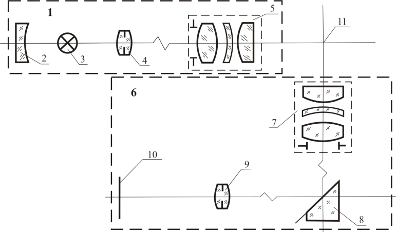
Figure 3. Optical Scheme of the Spectrometer «Masnik-A»:1-illuminating; 2-spherical mirror; 3-lamp lighting; 4,9-condenser with integrated field diaphragm; 5,7-projection lenses; 6-photometer; 8-mirror flat; 10-sensitive area of the photo detector; 11-space of work volume.
At the end of this section should be noted that the advantage of the developed by us aerosol spectrometer, compared with the currently operating appliances similar to [18], is the ability to change (operation unit) orifice size field illuminator and a photometer which in turn leads to a change the geometric dimensions of the working volume (or countable volume, see Figure 3) of the device, which can significantly extend the range of the measured aerosol number concentration of particles from the surrounding area, as well as the design concept of the spectrometer «Masnik-A» in the two blocks, the operation of which ensures the safety of the service operator from possible harmful effects of ambient aerosol.
- The Metrological Characteristics of a Multi-Channel Aerosol Spectrometer “MASNIK-A”
Metrological certification of multi-channel aerosol spectrometer «Masnik-A» was carried out according to a specially developed program AEL2.851.002PMA [19]. For certification identified metrological characteristics of the instrument are presented in Table. 3.
Table 3 : Metrological Parameters of the Equipment “Masnik-A”
| The Name of the Metrological Characteristics and Units of Measuring | Permissible Declinations |
| The relative error in the reproducibility of the calibration of the instrument at the reference desk of monodisperse aerosol particles, no more than | ± 15% |
| The relative error in the measurement aerosol particles sizes in the range from 0.4 to 40 , no more than | ± 20% |
A list of all assets, conditions and procedures, as well as a description of the measuring system for calibration certification set forth in [19].
The relative error in the reproducibility of the calibration of the instrument is determined by the formula:
![]() (10)
(10)
where d0 — nominal size of aerosol particles used reference, du — measured values of particles in micron. The deviation of the reproducibility of the calibration of the instrument was within ± 15%.
To assess the relative accuracy of measurement of dimensions of the aerosol particles, all operations were carried out as set out in [19] and a particle size of 0.5 microns.
According to the formula (3) is defined relative error of measuring the size of aerosol particles, which proved to be within ± 20%.
When the ambient temperature changes from -40 to 400 C additional error measure the size of aerosol particles does not exceed 20% of the relative error of measurement.
It should be noted that the above optical-electronic systems, we designed three patents for inventions.
Conclusion
The developed optical-electronic systems offer the possibility of remote sensing of physical and environmental parameters of the atmosphere and IR sources, as well as the aerosol component in the environment.
The experimental results of the metrological characteristics developed devices confirm the high accuracy of the measurements.
The developed method of infrared air monitoring can be widely used for remote environmental monitoring forest spaces and natural gas main pipelines.
Mobile version of the complex created instruments can be used successfully for the rapid assessment of physical and ecological state of the atmosphere, as well as for the distant researches of thermal objects.
References
[1] S.M. Musaelyan,The Problems of Clean Air. — Yerevan: Armenia, 1985 – 225 p. [2] A.G. Bannikov, A.K. Rustamov, The Nature Conservancy. 2nd ed., Rev. and add. — M. Agropromizdat, 1985 – 287 p. [3] O.S. Owen, Protection of Natural Resources / Transl. from English. — Moscow: Kolos, 1977– 416 p. [4] Y.T. Feldman,Hygienic Evaluation of Motor Vehicles as a Source of Air Pollution. — M., — 1975, – 187 p. [5] Laser Monitoring of Air Pollution: SO2, NO2, Ozone, Benzene, Toluene and Aerosols.- ELIGHT, Laser systems, GmbH, Berlin. — 2000. [6] A.A. Popov, S.V. Kachin, Computerized Analytical Systems for Environmental Monitoring.- Devices and control systems. -1994 — № 9 –p. 15-17. [7] R.S. Asatryan, S.R. Asatryan, G. Gevorgyan and others, Optical-Automatic Meteorological Office. — PTE. -2003 — № 4 –p. 125-126. [8] Guide to practice observing the runway visual range and sending messages about it, The International Civil Aviation Organization. Forward-scatter Meters. — Doc. 9328 — AN/908.- Ed. the second. — 2000 –p. 49-53. [9] R.S. Asatryan,Development and Manufacture of Optical and Meteorological Field Post-Machine («FOMPA»)- Report R & D (final) n / I-A-1376, № 0928-DSP, Yerevan.-1987-113 p. [10] R.S. Asatryan, S.R. Asatryan, Gevorgyan G.and others, Set the Meter Calibration Optical Transparency of the Atmospheree. — PTE.-2004 — № 6-p. 132-133. [11] R.S. Asatryan, R.A. Epremian, H.G. Gevorkyan and others, Universal Infrared Spectral Radiometer. — Intern. Journal of IR and MM Waves.-2003-V.24, № 6–p. 1035-1046. [12] R.S. Asatryan, Yu,A. Abrahamyan, H.G. Gevorkyan and others,IR Spectral Method of Monitoring the Industrial Gas Ejections in Atmospere. — Dubai Intern. Confer. on Atmospheric Pollution: 21-24 febr. 2004 — Dubai, UAE-2004.-Proceed. –p. 134-139. [13] Dual Channel Radiometer- Patent Internationally U. S. Pat. 3476914.-1998. [14] Ring Price filter for Tunable Optical Spectral Range from 1.8 to 5.6 Microns- OST-5683- 84. [15] R.S. Asatryan, Development and Manufacturing of Infrared Spectroradiometer «Wedge». – Report R & D (final) p/ya- A-1376: № 4115-DSP, Erevan.-1987–143 p. [16] R.S. Asatryan, S.R. Asatryan, L.A. Vardumyan. and others, The Multi-Channel Aerosol Spectrometer. — PTE.-2004 — № 4 –p. 166-167. [17] R.S. Asatryan, V.I. Sidorenko, The Optical Aerosol Spectrometer Calibration. — Proc. Reports. III Republic. Teach-tech. Conf. “New advances in instrumentation.”-Yerevan-1987–p. 29. [18] V.P. Shmargunov, V.V. Polkin, Counter Aerosol Particles on the Basis of A3-5. — PTE.-2007- № 2.-p. 165. [19] R.S. Asatryan, Design and Manufacture of Aerosol Spectrometer “Alternative”. -Report R&D (final) p/ya- A-1376: № 1228-CPD, Yerevan.-1986–128 p. [20] S.R. Asatryan, Method of Air Environmental Control Forest Spaces and Gas Pipelines. – Herald MANEB.-2011.-v.16.-: № 5.-MY. 2–p. 60-64.[schema type=»book» name=»OPTICAL-ELEKTRONIC EQUIPMENTS OF ECOLOGICAL DEDICATION AND STUDY OF THEIR METROLOGICAL PARAMETERS» author=»Asatryan Ruben, Khachatryan Norayr» publisher=»БАСАРАНОВИЧ ЕКАТЕРИНА» pubdate=»2017-05-25″ edition=»ЕВРАЗИЙСКИЙ СОЮЗ УЧЕНЫХ_ 30.01.2015_01(10)» ebook=»yes» ]